Chapter 1 LED
Description This chapter is the Start Point in the journey to build and explore ESP32-S3 WROOM electronic projects. We will start with simple “Blink” project
Project 1.1 Blink
In this project, we will use ESP32-S3 WROOM to control blinking a common LED.
Component List
ESP32-S3-WROOM x1
GPIO Extension Board x1
830 Tie-Points Breadboard x1
LED x1
Resistor 220Ω x1
Jumper Wire x2
Component knowledge
LED
Resistor
Breadboard
Connect
First, disconnect all power from the ESP32-S3 WROOM. Then build the circuit according to the circuit and hardware diagrams. After the circuit is built and verified correct, connect the PC to ESP32-S3 WROOM.
CAUTION: Avoid any possible short circuits (especially connecting 5V or GND, 3.3V and GND)! WARNING: A short circuit can cause high current in your circuit, generate excessive component heat and cause permanent damage to your hardware!

Sketch
According to the circuit, when the GPIO2 of ESP32-S3 WROOM output level is high,
the LED turns ON. Conversely, when the GPIO2 ESP32-S3 WROOM output level is low,
the LED turns OFF. Therefore, we can let GPIO2 circularly output high and low level
to make the LED blink.
Upload the following Sketch:
LAFVIN_Super_Starter_Kit_For_Esp32_S3\Sketches\01.1_Blink
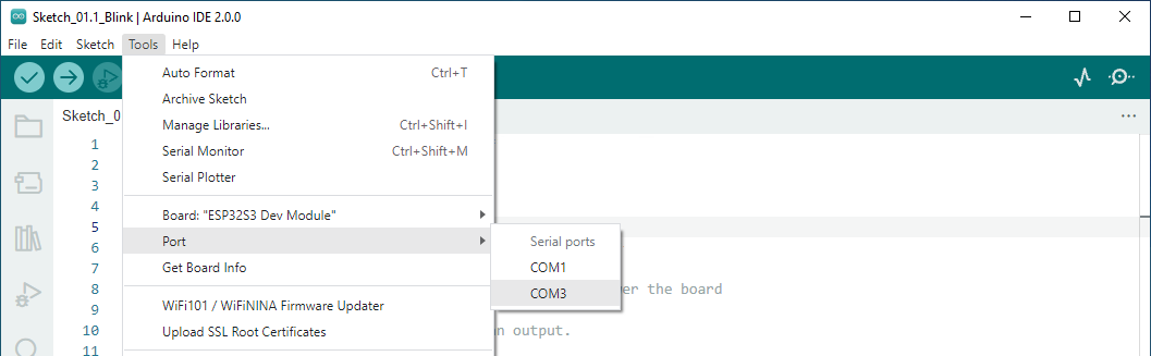
Before uploading the code, click “Tools”, “Board” and select “ESP32S3 Dev Module “.

Select the serial port. Note that the computer port number of each user may be different. Please select the correct serial port according to your computer. Taking the window system as an example, my computer recognizes that the communication interface of the ESP32-S3-WROOM is COM3, so I select COM3.
Note
Note: For macOS users, if the uploading fails, please set the baud rate to 115200 before clicking “Upload Using Programmer”.

Sketch_01.1_Blink Click the Upload button and it will compile and upload the Sketch to the ESP32-S3-WROOM.

Wait for the Sketch upload to complete, and observe the ESP32-S3 WROOM. You can see that the LED on breadboard flashes cyclically.
