Chapter 10 Potentiometer & LED
Earlier we have learned the use of ADC and PWM. In this chapter, we will learn how to use a potentiometer to control the brightness of an LED.
Project 10.1 Soft Light
In this project, we will make a soft light. We will use an ADC Module to read ADC values of a potentiometer and map it to duty cycle of the PWM used to control the brightness of a LED. Then you can change the brightness of a LED by adjusting the potentiometer.
Component List
ESP32-S3-WROOM x1
GPIO Extension Board x1
830 Tie-Points Breadboard x1
Resistor 220Ω x1
Potentiometer(10k) x1
LED x1
Jumper Wire x5
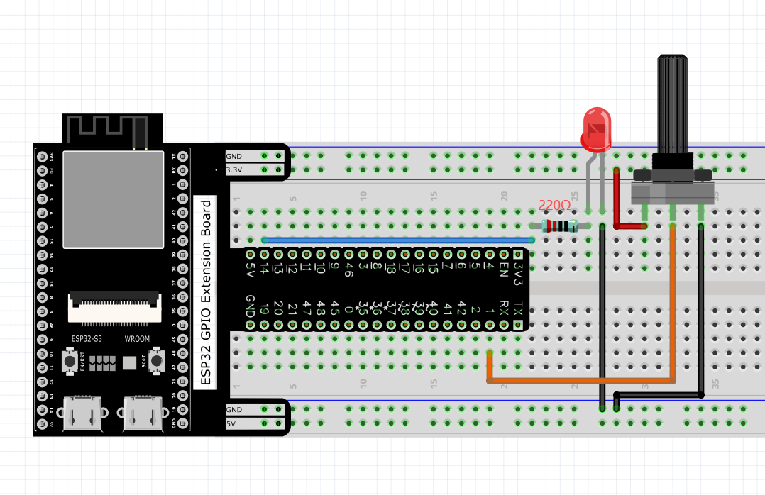
Connect
Sketch
Sketch_10.1_Softlight

Download the code to ESP32-S3 WROOM, by turning the adjustable resistor to change the input voltage of GPIO1, ESP32-S3 changes the output voltage of GPIO14 according to this voltage value, thus changing the brightness of the LED.
Code
The following is the program code:
#define PIN_ANALOG_IN   1
#define PIN_LED         14
#define CHAN            0
void setup() {
ledcAttachChannel(PIN_LED, 1000, 12, CHAN);
}

void loop() {
int adcVal = analogRead(PIN_ANALOG_IN); //read adc
int pwmVal = adcVal;        // adcVal re-map to pwmVal
ledcWrite(PIN_LED, pwmVal);    // set the pulse width.
delay(10);
}
In the code, read the ADC value of potentiometer and map it to the duty cycle of PWM to control LED brightness.
Project 10.2 Soft Colorful Light
In this project, 3 potentiometers are used to control the RGB LED and in principle it is the same as the Soft Light project. Namely, read the voltage value of the potentiometer and then convert it to PWM used to control LED brightness. Difference is that the original project only controlled one LED, but this project required (3) RGB LEDs.
Component List
ESP32-S3-WROOM x1
GPIO Extension Board x1
830 Tie-Points Breadboard x1
Resistor 220Ω x3
Potentiometer(10k) x3
LED-RGB x1
Jumper Wire x13
Connect

Sketch Sketch_10.2_SoftColorfulLight
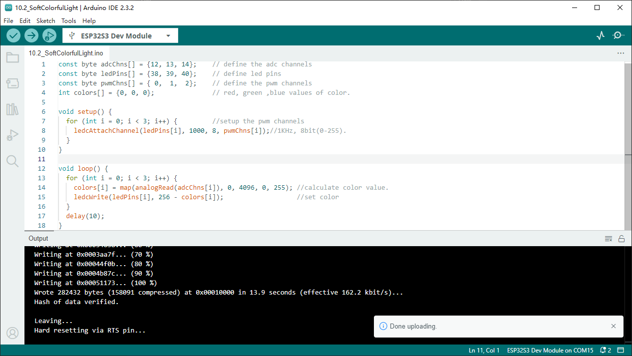
Download the code to ESP32-S3 WROOM, rotate one of the potentiometers, The corresponding led colors will change: 38 control red, 39 control green, 40 control blue.
Code
The following is the program code:
const byte adcChns[] = {14, 13, 12};    // define the adc channels
const byte ledPins[] = {38, 39, 40};    // define led pins
const byte pwmChns[] = { 0,  1,  2};    // define the pwm channels
int colors[] = {0, 0, 0};               // red, green ,blue values of color.

void setup() {
for (int i = 0; i < 3; i++) {         //setup the pwm channels
    ledcAttachChannel(ledPins[i], 1000, 8, pwmChns[i]);//1KHz, 8bit(0-255).
}
}

void loop() {
for (int i = 0; i < 3; i++) {
    colors[i] = map(analogRead(adcChns[i]), 0, 4096, 0, 255); //calculate color value.
    ledcWrite(ledPins[i], 256 - colors[i]);                   //set color
}
delay(10);
}
In the code you can read the ADC values of the 3 potentiometers and map it into a PWM duty cycle to control the 3 LED elements to vary the color of their respective RGB LED.